SILTRONIX 1011B Betriebsanleitung
Stöbern Sie online oder laden Sie Betriebsanleitung nach Mikrofone SILTRONIX 1011B herunter. SILTRONIX 1011B Operating instructions Benutzerhandbuch
- Seite / 32
- Inhaltsverzeichnis
- LESEZEICHEN
- Downloaded by 1
- RadioAmateur.EU 1
- ~ ,...,. y 4
- POWER CONNECTOR 5
- CONNECTIONS 6
- I CAUTION I 7
- AM TRANSMITTER TUNING 8
- VOICE TRANSMISSION (SSB) 8
- GENERAL DISCUSSION 9
- SIGNAL GENERATION 9
- FREQUENCY CALIBRATION 11
- -,;'1t 12
- 10 watts 16
- 1 210 12.6AC 220 17
- 3. Microphone defective 18
- [PARTS LIST I 19
- TRANSISTORS 19
- WARRANTY POliCY 21
- ~..- ...~. 21
- 2Mr ~I. ~I' _~I' 24
- ':" 26
Inhaltsverzeichnis
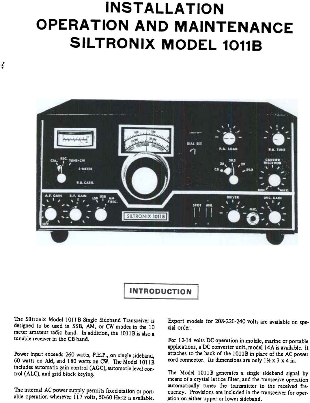
,..The Siltronix Model 1011 B Single Sideband Transceiver isdesigned to be used in SSB, AM, or CW modes in the 10meter amateur radio band. In addition
~I I~V4POWERAMP6LF6V2TRANSMIX12BE6V3DRIVER6GK6LANT~j- IV7FIRSTIFAMP12BA6V10AGC/ALCAMP6AV6Q3CAR OSC2N706VlVFO AMP12BA6PI NETL_- __II IIV14BAF AMP1
of the First IF Amplifier is controlled through the Auto-matic uvel Control (ALC) network (using the AGC Ampli-fier VIO) to control
Authorities agree that the average voice power is 20 to 20 dbbelow peak voice power. Normally, some peak clipping inthe power amplifier can be tolera
Dle alignment procedures presented in this section are rou-tine touch-up procedures for all tuned circuits and otheradjustments. It is r
FIGURE 6. SILTRONIX MODEL 10118 TOP VIEW.14Downloaded byRadioAmateur.EU
for the meter to "peak" above the 100 ma. plateauon ei ther side of resonance. If there is such a peak,adjust C40l, the P.A NEUTRALIZING
TABLE 1. VOLTAGE AND RESISTANCE MEASUREMENTSVoltage measurements were taken using a HEWLETT PACKARD Model 410C/B VTVM. Resistance meas
TABLE 2. TROUBLESHOOTING GUIDEDEFECTPOSSIBLE CAUSEP A Idling CurrentUnstable1. Defective Power Amplifier Tube (V4).2. Defective BIAS control and/
[PARTS LIST IRlOO6RlOO7RlOO8RIOO9RlIOlRII02RII03R1104RII05R1201R1202R1203R1301R1302R1303R1304R1305R1306R1307R1308R1309R1310R1311R1312R1313R1401Rl402
REAR PANEL CONTROLS AND CONNECTIONSP.A. BIAS Potentiometer, AUX RELAY jack, CW KEYjack, Outboard VFO Connector, HEAD PHONES jack,Fuse Holder, Antenn
CI08.CI09ClIOC111.C201C202C203" C204C205C2A, C2BC302C303C304C305C401C402C403C404C40SC4Q6..~.C407 .C408C409C410C501C502C503C601C602C603C701C702
WARRANTY POliCYSilt."On~ Corporation walTants this equipment againstdef~ts in material or workmanship, except for tubes,transistors, and di
Downloaded byRadioAmateur.EU
Downloaded byRadioAmateur.EU
T.--"1~~~~~~.~J- .RCA-.,-.------'"\..1-~~-I--J I".--I cms2Mr ~I. ~I' _~I'0 i..- K0 i .-0 Dl111 ~..I, ~II II
~Il11:...:-J':"---1Z/»
GENERALMOBILE INSTALLATIONThe installation of the Siltronix 1011 B is not at all difficult,and it involves only the placement of the transce
Downloaded byRadioAmateur.EU
I';;:::j ~ ~--~'~--0--~ " ..;;:::I~~, ALTERNATEBRACKETLOCATION,... ~~<"I.~.-.; ,,:~~"""~.\\~~\'f}#6 x
ANL SwitchAutomatic Noise LimiterSPOT SwitchInserts carrier for AM tuning in REC position.Meter SwitchReads cathode current in P.A. CATHODE positio
0 Carefully adjust the DRIVER and the P.A. TUNEcontrols for maximum receiver noise.Before connecting any cables to the Siltronix lOll B trans-ceive
TRANSMITfER TUNING STEPS3. Your Siltroni.x 1011B will automatically transmit onexactly the same frequency as the one to which you arel
b. IMMEDIATELY rotate P.A. TUNE control formaximum meter reading. -nus is the critical"resonating" adjustment which must be don
GENERAL DISCUSSIONfollowing manner. Carrier is generated by Q3 Carrier Oscil-lator, which is a Pierce oscillator with the crystal operatingin parall
© 2020, manymanuals.de. Alle Rechte vorbehalten. | 0.588 s |
 Manymanuals.com
 Manymanuals.de
 Manymanuals.fr
 Manymanuals.it
 Manymanuals.pl
 Manymanuals.cz
 Manymanuals.es
 Manymanuals-pt.com
Kommentare zu diesen Handbüchern